
Now remove the 2 screws that are holding the cover in place on the left side and slide it off. You will need a Phillips screwdriver to do this.

Here we are using a standard mid tower case and will only be removing the left side to access the computer. Once this is done, you will open the case to your computer. When replacing a power supply one of the first things you want to do is unplug the computer from the wall and remove the power cable from the back of the computer/power supply.

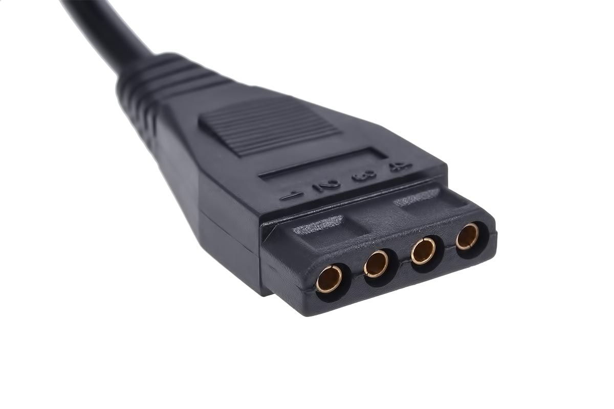
If your power supply is still good you will need to reconnect everything and make sure the computer boots up fine and still works. At this point, if you have determined that your power supply is not working properly you will want to replace it. Then turn off the power supply by using the switch on the back of the power supply by turning it to the off position and don’t forget to unplug the P1 plug from the motherboard. Once you have finished testing remove the probes from the P1 plug and turn off your meter. The yellow wire is a 12 volt wire and should read somewhere between 10.8 volts and 13.2 volts. Now remove the red probe from the red wire and connect it to the yellow wire. Once again since this is a red wire, it is a 5 volt wire and should read somewhere in the range of 4.5 to 5.5 volts. Then place the red probe into the red wire. The blue wire is a (negative) -12 volt wire and should read somewhere between -10.8 volts to -13.2 volts. Now test the blue wire by removing the red probe from the orange wire and sliding it into the P1 plug where the blue wire is. Since the orange wire is a 3.3 volt wire it should read somewhere between 3.0 volts and 3.63 volts. Start by testing the orange wire by placing the red probe into the back of the P1 plug where the orange wire is. Once the ground is in place you can leave it there while we test the other wires. PN# 39-01-2240 or equivalent" - another, different, "Molex" power connector.Now to test the P1 (10x2) 20 pin plug you will want to slide the black probe into one of the black (ground) wires in the back of the P1 plug while it is still connected. Make sure it goes down far enough to make contact. Note also that the main 24-pin power connector (§ 4.2.1) is specified as "Molex* Housing: 24 Pin Molex Mini-Fit Jr. Note that AMP and Molex are two different manufacturers, and those are just part numbers. The ATX power supply specification actually refers (§ 4.2.2) to them as a " peripheral connector", specified as "AMP* 1-480424-0 or Molex* 15-24-4048 or equivalent". Your first pictured connector is actually a PATA/IDE ribbon data cable. Despite the different names, they are the same thing. Therefore, a power connector referred to as a "PATA" or "IDE" power connector is likely to be a "Molex 4-pin power connector" or "peripheral power connector" and looks like your latter pictures. It was most commonly used with pre-SATA hard drives, which are nowadays referred to as PATA (previously called IDE) drives. The 4-pin power connector that is commonly called a "Molex connector" is really more a general purpose peripheral power connector that delivers 12 V and 5 V power. Including the main 24-pin ATX motherboard power connector! And companies other than Molex also make the connector you know as a "Molex connector", notably AMP but also many unbranded/generic ones are also available. "Molex connector" is actually a rather imprecise term, since the Molex company makes many, many different connectors.


 0 kommentar(er)
